Mounting bias calibration
The mounting bias refers to the initial deviation from the horizontal position in which the GPS receiver is installed on the roof of the vehicle. The following factors may influence and alter the mounting bias:
- Tyre pressure
- Track tension
- Dual wheels
- Tyre sizes
- Cab suspension
- Repairs to cab (to suspension and mountings)
- Removal and refitment of receiver
- Altered original mounting position
Note: The mounting bias calibration procedure must be performed in the event of any of the changes listed above or at least once every 6-12 months.
Calibrating the mounting bias is recommended if Autonomous is selected as the Correction Source, even if it is indicated as not necessary in the screen.
This calibration procedure must be performed in an open space at a suitable distance from any obstacles. If the receiver is not installed level, this calibration will adjust its effective position.
WARNING: Make sure that there is sufficient space in front of the vehicle to drive forward at least 70 meters (230 feet) in a straight line and to turn the vehicle around at the end of the wayline.
- Select:
 / Autosteer options Menu
  / Calibrate auto-steering
  .
.
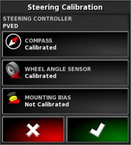
The Autosteer calibration screen is displayed.
- Select MOUNTING BIAS. If the component is indicated as already calibrated, perform the procedure anyway if the receiver has not been calibrated on this vehicle.
Note: To calibrate the mounting bias, guideline points "A" and "B" are plotted along the wayline with the vehicle driven at 2 kph (1.2 mph) for 70 m (230 ft). At the end of the pass, the operator must turn the vehicle around and repeat the procedure. To start the next stage of the calibration process, the vehicle must pass within a distance of 30 cm from flag points "A" and "B".
- Take the vehicle back to an open space. When you are ready to start the procedure, select
 to highlight flag point "A".
 - Drive forward in a straight line. Point "B" will be created automatically when the field 'Distance to A' shows 70 m (230 ft).
- Turn the vehicle around and acquire the newly plotted guideline - the track number should read "0".
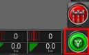
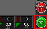
- Select Engage autosteer from the Operations screen to steer along the wayline. The colour of the autosteer icon changes to green, an audible signal sounds and a warning message flashes on the screen to indicate that the autosteer function has been activated.
If it is not possible to activate the autosteer function when the Autosteer option is displayed, the 'Autosteer status' box is displayed.
- Resolve the problems identified by the red indicators before starting the mounting bias calibration procedure (resolve problems in the order listed, starting from the top of the screen).
- Drive the vehicle to the flag point "B" created during the calibration procedure.
- Set a vehicle speed of 2 kph (1.2 mph).
- Steer along the guideline back to the flag point "A" created previously.
When the 'Distance to A' field shows 50 m, the blue line of the calibration progress bar should start moving while the percentage value increases.
When the calibration progress bar reaches 50%, the calibration bar stops and the percentage will remain at 50%.
This means that the system has sufficient data for the first stage of the calibration procedure, and at this point, mounting bias calibration is suspended.
- Proceed to point "A".
- Once you have passed the point "A", turn the vehicle round.
- Acquire track "0" and engage autosteer again.
- Drive though flag point "A" in the opposite direction.
- Set a vehicle speed of 2 kph (1.2 mph).
- Steer along the wayline to return to the flag point "B" created previously.
When a value of 50 m is indicated in the 'Distance to B' field, the blue calibration progress bar should start moving from the 50% position, while the percentage value increases.
When the calibration progress bar reaches 100%, this means that the system has sufficient data for the second stage of the calibration procedure. The mounting bias calibration procedure is now interrupted.
- Proceed to point "B".
- Stop the vehicle. Calibration of the mounting bias has been completed successfully.
- Confirm
 to return to the calibration screen.
The Steering Calibration screen indicates the calibration status of the compass, the wheel angle sensor and the mounting bias.
- Confirm to return to the previous screen.
The indicators in the Autosteer Status window will now all be green.